1. The Electrochemistry of Metallic Lithium Plating Below 32°F (0°C)
Lithium Iron Phosphate ($\text{LiFePO}_4$) is the safest, longest-lasting battery chemistry in off-grid engineering, routinely delivering 4,000 to 6,000+ cycles at 80%–85% Depth of Discharge. Yet a brand-new \$1,000 LiFePO4 battery can lose 30% of its permanent capacity in a single sunny January morning if charged while the internal electrolyte is below 32°F (0°C).
During normal charging above 41°F (5°C), lithium ions ($\text{Li}^+$) de-intercalate from the $\text{LiFePO}_4$ cathode, migrate through the organic carbonate electrolyte, pass through the Solid Electrolyte Interphase (SEI) layer, and smoothly slip between the atomic layers of the porous graphite ($\text{C}_6$) anode to form $\text{LiC}_6$.
When cell core temperature drops below 32°F (0°C), two kinetic bottlenecks collide:
- Electrolyte Viscosity & SEI Desolvation Barrier: The ethylene carbonate / dimethyl carbonate (EC/DMC) liquid electrolyte thickens significantly below freezing, and the activation energy required to strip the solvation shell off $\text{Li}^+$ ions at the anode's SEI boundary spikes by 300% to 500%.
-
Solid-State Diffusion Bottleneck in Graphite: When your solar MPPT controller wakes up at 9:00 AM on a crisp 15°F winter morning and pushes
0.15C to 0.30C(e.g., 45A–90A into a 300Ah battery), $\text{Li}^+$ ions arrive at the graphite anode surface faster than they can diffuse inward between the graphene sheets. -
Metallic Lithium Dendrite Deposition: Because the anode local potential drops below
0.0V vs. Li/Li+, the backed-up lithium ions accept electrons right on the outer surface of the anode and electroplate as shiny metallic lithium ($\text{Li}^0$) needles and dendrites. Plated metallic lithium never re-intercalates—it permanently locks away active lithium inventory (causing immediate capacity fade) and grows sharp crystalline needles that can puncture the polymer separator and trigger an internal short circuit.
2. Why Bluetooth BMS Cutoffs Alone Leave You in the Dark (And How Internal Silicone Heaters Work)
Many budget LiFePO4 batteries advertise "Low-Temperature BMS Protection." While a passive NTC thermistor cutoff saves the cells from plating, it creates a catastrophic operational failure in unheated off-grid cabins, RVs, and vans:
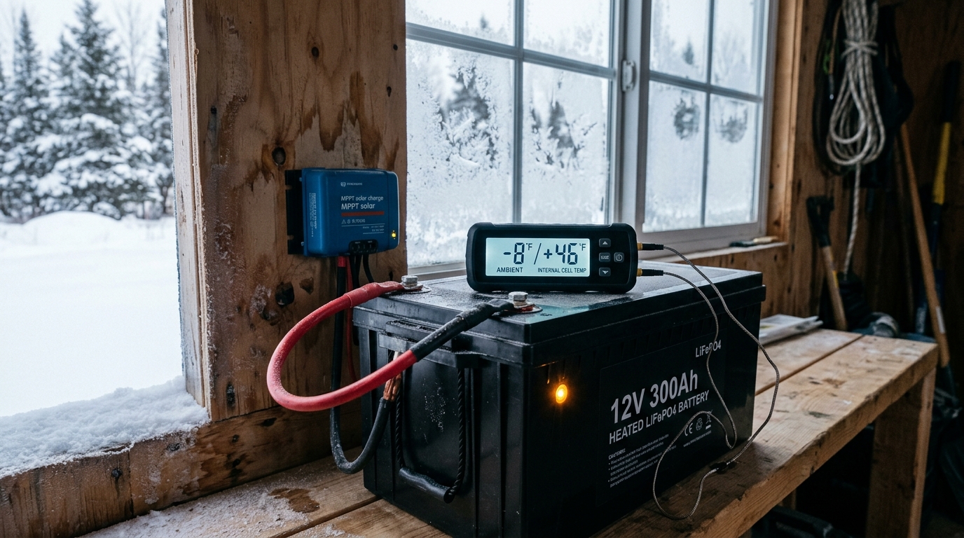
Imagine your unheated cabin battery compartment drops to 24°F overnight while running a 12V diesel heater, refrigerator, and Starlink. At 8:00 AM, bright winter sun hits your solar panels. A passive BMS sees T_cell = 24°F (< 32°F) and holds its Charge MOSFET (C-FET) open. Your solar array sits at 100% open-circuit doing nothing for 6 hours of prime sunshine while your appliances continue draining the battery through the Discharge MOSFET (D-FET). By Night 2, the battery hits its 10.0V Low-Voltage Disconnect and your cabin freezes.
How Internal BMS Silicone Heating Pads Route Solar Current
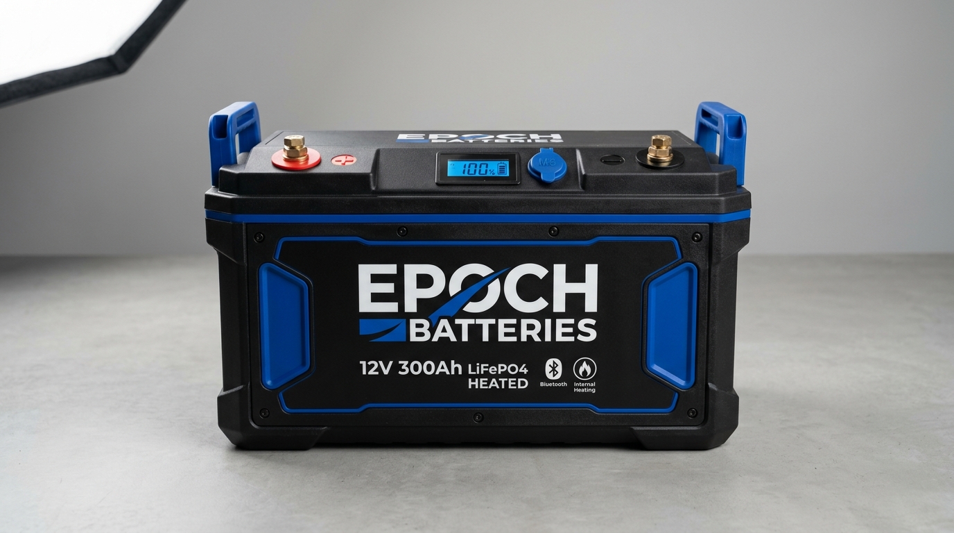
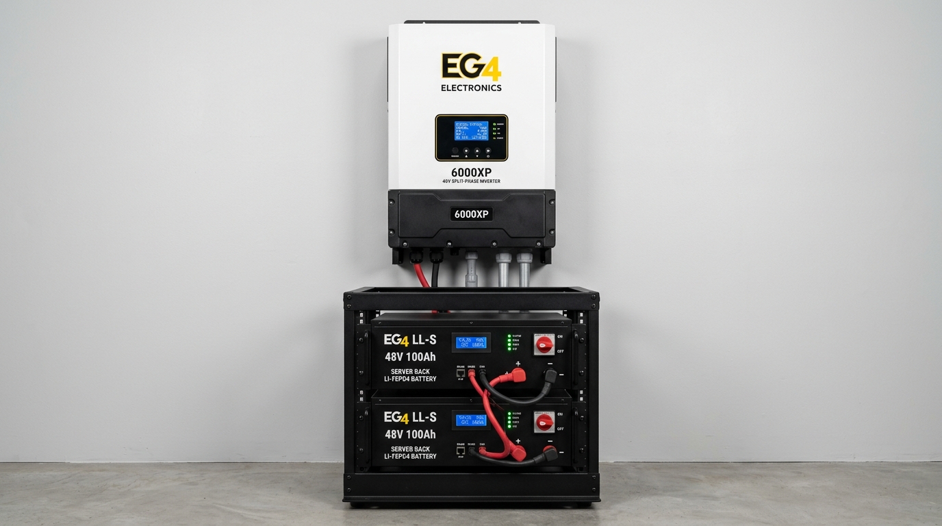
In Tier 2 and Tier 3 cold-weather batteries (such as the Epoch 12V 300Ah Heated and EG4 Indoor Heated 48V Server Rack), laminated polyimide/silicone resistive heating films are bonded directly against the wide aluminum faces of the prismatic LFP cells inside the insulated case:
The moment your solar MPPT controller or vehicle alternator applies charging voltage (>13.4V DC) and current (>1.5A), the BMS senses cell temperature below 32°F. It keeps the main cell Charge MOSFET OPEN (0.0A entering the LFP cells) and closes the dedicated Heater MOSFET (H-FET).
Incoming solar current (typically 8A to 12A @ 12V, or 110W–160W) is routed 100% through the internal silicone heating pads. Because the heaters press directly against the aluminum prismatic cans inside a sealed enclosure, zero energy is wasted heating the surrounding room air—raising internal cell temperature from 15°F to +41°F in just 25 to 35 minutes.
Once the internal thermistor confirms the cell core has reached +41°F (+5°C) (or +50°F / 10°C on some server racks), the BMS opens the heater circuit and closes the Charge MOSFET—seamlessly transitioning the full 50A–100A solar harvest into bulk battery charging. Furthermore, exothermic $I^2R$ internal resistance during bulk charging keeps the cells warm for the rest of the afternoon.
3. Cold-Weather Solar Array $V_{oc}$ Hyper-Spike Math (NEC Table 690.7(A))
While lithium batteries hate cold charging, silicon photovoltaic solar cells experience the opposite physics: as ambient temperature drops below the 77°F (25°C) Standard Test Condition (STC), solar panel Open-Circuit Voltage ($V_{oc}$) climbs sharply.
Before sunrise on a crystal-clear sub-zero morning, your solar panels are cold-soaked to ambient air temperature. At first light, solar irradiance hits the silicon wafers before the MPPT controller has pulled enough current to load down the voltage. If the cold-multiplied series string voltage exceeds your MPPT charge controller's absolute maximum input ceiling (e.g., 150V, 250V, or 480V DC) by even 2 volts, the controller's input capacitors and FETs suffer catastrophic dielectric breakdown (magic smoke—never covered under warranty).
| Record Low Ambient Temp (°F) | Record Low Ambient Temp (°C) | NEC Table 690.7(A) Factor | "120V STC" Array Actual Cold Voc | "240V STC" Array Actual Cold Voc | Safe on 150V / 250V MPPT? |
|---|---|---|---|---|---|
| +32°F to +40°F | 0°C to +4°C | 1.10x | 132.0 V | 264.0 V | 150V OK / 250V FAILS! |
| +14°F to +23°F | -10°C to -5°C | 1.12x | 134.4 V | 268.8 V | 150V OK / 250V FAILS! |
| -4°F to +5°F | -20°C to -15°C | 1.16x | 139.2 V | 278.4 V | 150V OK / 250V FAILS! |
| -13°F to -22°F | -25°C to -30°C | 1.18x – 1.20x | 141.6 – 144.0 V | 283.2 – 288.0 V | 250V MPPT DESTROYED |
| -31°F to -40°F | -35°C to -40°C | 1.23x – 1.25x | 150.0 V (LIMIT!) | 300.0 V | BOTH 150V & 250V FAIL |